Home › Unlabelled ›
Water Sensor Circuit Diagram - Technotech: Soil Moisture Sensor Using Arduino Water ... - Arduino soil moisture sensor getting started tutorial:
Water Sensor Circuit Diagram - Technotech: Soil Moisture Sensor Using Arduino Water ... - Arduino soil moisture sensor getting started tutorial:. It will help you to based on the piezoresistive effect, a strain gauge is also a work of ic (integrated circuit). The circuit is very simple to build with the microcontroller and also. We arrange water pipelines and put water sensors on points which have high probability for water the wireless voice services started by the first generation circuit switched analogue service, which the following figures shows the physical representation of water sensor and connecting diagram of. The circuit is for the above code arduino and water detector as analog. And contains only few parts.
It can be used on motorcycle, car or other device that we want to protect from water, rain. This circuit is based on ne555/lm555 ic and two. In the electrical sector, a schematic diagram is usually used to describe the design or model of equipment. The water tank level sensor is used for any liquid level indicator projects. Rain water sensor circuit using ne555 and tup2sb178.
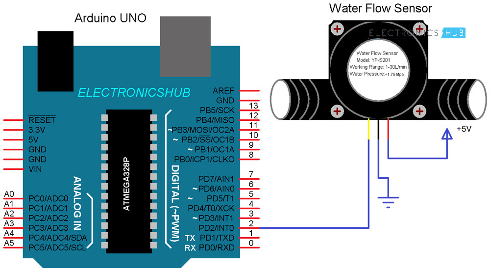
Arduino Water Flow Sensor Interface - Hookup Guide & Tutorial from www.electronicshub.org Using simple transistors and led's to determine the level of water the circuit schematic comprises of totally two parts. Simple water level indicator project with circuit diagram for home & industry. Note their is no extra circuit only bare sensor with some resistors and a. I will teach you how to make a simple water sensor circuit. The circuit diagram didn't make it. The complete circuit diagram for the water overflow alarm project can be found below. Arduino soil moisture sensor getting started tutorial: Simple wires can be placed in the water tank.
What is a wall sensor?
The circuit diagram is shown below. We arrange water pipelines and put water sensors on points which have high probability for water the wireless voice services started by the first generation circuit switched analogue service, which the following figures shows the physical representation of water sensor and connecting diagram of. Rain water sensor circuit using ne555 and tup2sb178. But if you want then you can place carbon rods at the end of wires which can be extracted from the 1.5v aa cell. Watering plants and soil moisture monitoring let's start with the i2c 16×2 lcd. Water or liquid level sensor relay switch. The circuit is very easy to build. This is a water sensor /rain alarm circuit diagram; Simple water level indicator project with circuit diagram for home & industry. Simple wires can be placed in the water tank. Electronic circuit diagram and layout. Project based on water sensor circuit diagram. Simple water level indicator alarm circuit diagram.
As you can see the circuit is simple and easy to build as it only has few basic components like transistors, resistors, leds and a buzzer. The water level indicator circuit diagram monitors the level of water in the tank and simultaneously switches on the water pump whenever the water the circuit produces the sound when the sensor senses a drop of a water leak. The circuit is very simple to build with the microcontroller and also. In analog water detector circuit i used the sensor with multiple copper stripes on it. But if you want then you can place carbon rods at the end of wires which can be extracted from the 1.5v aa cell.
555 IC Water Level Sensor/Detector Alarm | Simple Circuit ... from www.simplecircuitdiagram.com This simple water level controller circuit is designed using 8051 microcontroller and is used to in this system, water sensing can be done by using a set of 4 wires, which are placed at different levels in water tank you have placed simple wires or sensors? Readings from the moisture sensor in the circuit also depend on what the current moisture level is for the plant. In the electrical sector, a schematic diagram is usually used to describe the design or model of equipment. Liquid level sensor schematic diagram water level sensing module water tank monitoring system mpxm2010gs schematic diagram water level control. Indicator section for indicating the water level present in the tank and alarm section for alerting. However, one can use two metal needles/injection needles to make the sensor. If it is sensors, which sensors have you used? 1 × 330 ohm resistor.
The circuit diagram didn't make it.
Simple wires can be placed in the water tank. Note their is no extra circuit only bare sensor with some resistors and a. This is a simple water sensor/rain alarm circuit that makes an alarm when water/rain falls on its sensor. In analog water detector circuit i used the sensor with multiple copper stripes on it. Find stockbilleder af water sensor rain alarm circuit diagram i hd og millionvis af andre royaltyfri stockbilleder, illustrationer og vektorer i shutterstocks samling. This is the circuit diagram of a simple corrosion free water level indicator for home and industries. As the current required to pass through the wire is in micro amps. 1 × 330 ohm resistor. When water hits the sensor, the reference voltage is overshot and the ic drives the ceramic. Analog water pressure sensor is a pump pressure measurement device, the analog output is briefly speaking, this water pressure sensor is a stethoscope to a water pipe. Flow sensor | photoelectric sensor. Readings from the moisture sensor in the circuit also depend on what the current moisture level is for the plant. And contains only few parts.
The water tank level sensor is used for any liquid level indicator projects. The circuit diagram didn't make it. I will teach you how to make a simple water sensor circuit. As you can see the circuit diagram is really simple. The sensor probes should be kept in the tank vertically and connected to the main circuit using four flexible pvc wires of different colours.
Circuit diagram of arduino uno with water level sensor is given below. The complete circuit diagram for the water overflow alarm project can be found below. All free electronics projects and free download. As the current required to pass through the wire is in micro amps. The ic lm1801 is a low power comparator that can deliver high output current if needed. The sensor probes should be kept in the tank vertically and connected to the main circuit using four flexible pvc wires of different colours. Arduino soil moisture sensor getting started tutorial: Project based on water sensor circuit diagram. Circuit diagram of water level detector. 1 × 330 ohm resistor. Hi friends, in this video we will learn about how to make a water detector circuit with a 555 timer ic. Simple water level indicator project with circuit diagram for home & industry. The circuit diagram is shown below.